Disaster Recovery Inside-Out for Dummies (with LSI)
In this article, I'd like to document a setup I have been working on for a few days at the LSI office in Milano (great guys and free beverage there! Thanks!). LSI is the company from which IBM OEMs the DS3000, DS4000 and DS5000 lines of storage servers. Since I am trying to get a little bit more into the storage and network subsystems I wanted to spend a few days playing with those kits. I have concentrated on today's hot topic of Disaster Recovery and particularly the integration of LSI RVM (Remote Volume Mirroring) into the VMware SRM (Site Recovery Manager). I have to admit that I am not a storage guru, nor I have looked too much into SRM, so most of the stuff you will find here might be pretty basic. This is clearly not an advanced read for the likes of Duncan Epping, nor for those that go to bed with the VMware vmkfstools CLI or "talk UUID." (I guess Duncan will get what I mean.) Yet it's intended to provide a bit of background about what happens behind the scenes (the "scenes" would be the GUIs of the various products involved in this case). The SRM part is really focused on the storage integration which was the thing I was most interested in for this 2-days storage marathon. I like to treat these articles as a sort of personal log / documentation of what I have done (for future reference) so it will certainly serve me in the long run. Hopefully it will be of use for some of you, too.
Last but not least while the bar on the right of your browser might suggest this is a long post... consider that it's full of screenshots! So without further adieu, let's get started.
Basic Remote Mirror Setup
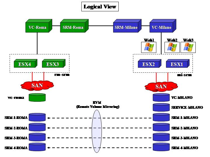
This part doesn't involve any specific SRM concept in action. It's just meant to describe the basic infrastructure setup (both logical and physical) as well as the way the storage replicates and how the VMware hosts deal with replicated LUNs. It is important to understand what happens at a lower level in order to move on and plug SRM on top of this. The picture below outlines how the logical layout of the infrastructure looks (including SRM):
For completeness, the following picture describes how the physical infrastructure looks instead:
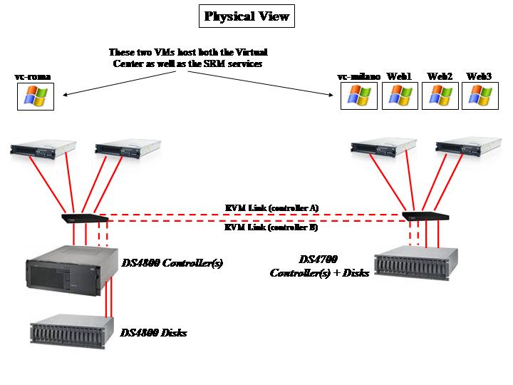
As the picture outlines, the Virtual Center VMs in both sites also host the SRM service. Depending on the scale of your project you might want to have dedicated virtual machines to host the SRM instances or even dedicated physical servers. Milano, in our lab scenario, is the primary site while Roma is the DR site. As you can imagine, LUNs need to be replicated from the DS4700 in Milano onto the DS4800 in Roma. LSI calls this storage feature RVM (Remote Volume Mirroring) and it's essentially an advanced function that allows you to keep a copy of your LUNs on a remote storage server.
Notice that the DS4700 is a storage server that includes into a single 3U package both the controllers (A and B) as well as the first string of disks (more can be attached through FC ports on the rear). On the other hand, the DS4800 has a 4U "head" unit that hosts the controllers but doesn't include any disk in the base chassis. They can be added with external expansions (as in the picture above). You might guess that the 4800 is a more powerful machine than the DS4700 and that, in a real life scenario, you might want to have that situation inverted. Your guessing is correct but for the sake of the tests this wasn't interesting since we weren't looking for ultimate performance. Also consider that any DS4xxx type of storage is "replication compatible" both ways with any other DS4xxx type of storage. And even DS5xxx!
Note: Other than the standard zoning so that each of the servers with two HBAs can see each of the two controllers on the storage array, please consider that for the RVM feature to work all controllers need to be connected in a certain way. Specifically for this scenario the last FC port of ControllerA on the DS4700 needs to be connected to the last FC port of ControllerA on the DS4800. Same zoning process for ControllerB. Without this extra SAN configuration RVM would not work. And no, having a single switch per site is not a best practice - you would need two in a real life environment.
The storage configuration (a summary of it) is described in the pictures below. Basically the DS4700 in Milano has a couple of LUNs that are dedicated to the local cluster and that do not replicate (these are VC-MILANO and SERVICE-MILANO). These LUNs host the Virtual Center instance as well as a Windows template. There are other LUNs (SRM-1-MILANO, SRM-2-MILANO, SRM-3-MILANO and SRM-4-MILANO) that are replicated onto the DS4800 in Roma. A simple synchronous mirroring configuration has been established.
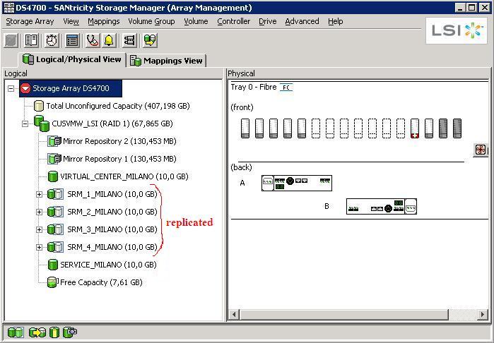
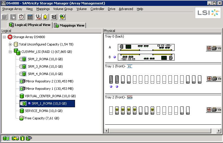
The way you set this up is that you first create companion LUNs on the target: they need to be at least as big as the source LUNs, or bigger if you want.
Through the LSI Storage Manager (SANtricity) you then select the source LUN and you mirror it onto the remote storage: a list of DSxxx storage devices with the mirroring feature enabled is shown, as well as a list of compatible companion LUNs for each device. The DS4800 does not mask the replicated LUNs to the cluster in Roma. This means that the hosts in the cluster have no idea whatsoever that there are LUNs on that array that are in sync with the cluster in Milano. In our lab we have manually created SRM-1-ROMA, SRM-2-ROMA, SRM-3-ROMA, SRM-4-ROMA on the DS4800 (as you can see in the picture above) and then we went through the steps described to create the mirror.
Now that the replication is in place, the first test we did at the storage infrastructure level was to create a snapshot of a replicated LUN. From the Storage Manager we created a snapshot of SRM-1-ROMA leaving the mirror link between SRM-1-MILANO and SRM-1-ROMA in place as the picture below suggests:
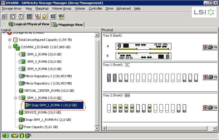
This is how you would read the above picture: SRM-1-ROMA is a replica of a LUN coming from another storage server. As such it's in a read-only state (in fact you don't want to write onto it since it's continuously being updated by its master LUN on a remote storage). However, we took a snapshot of that R/O LUN at a certain point in time and we called it Snap-SRM-1-ROMA-1. This LUN is now enabled for R/W so it could be fully used as a point in time copy of an R/O LUN under replication.
The next step was then to manually map this snapshot to the cluster in Roma so the servers would be able to recognize it:
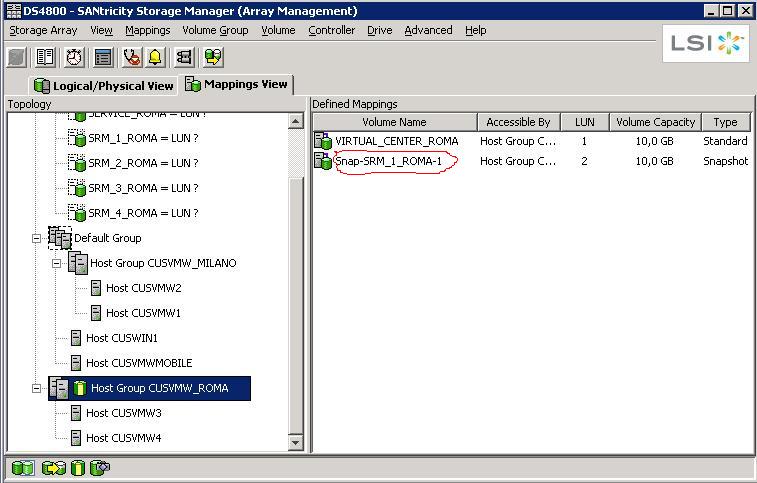
And this is when the "fun" begins.
*** Background information that you need to understand and be familiar with before you move on ***
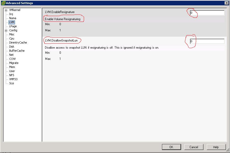
There are two key parameters that rule how an ESX host deals with the LUNs:
- EnableResignature (default = 0 = False)
- DisallowSnapshotLUN (default = 1 = True)
It took me a while to digest them (and right now I think I am halfway to it), but essentially the DisallowSnapshotLUN (when active, which is the default) instructs the ESX host NOT to import the VMware Datastore if it recognizes it's a snapshot of an existing LUN. When the parameter is turned off to False the ESX host is allowed to import the snapshot as a VMware Datastore without modifying its original name or its UUID.
The first parameter (when active, which is NOT the default) instructs the ESX host to resign the LUN and import it into the ESX host as a new VMware Datastore (which gets labeled snap-xxxxxx-
These parameters get very important (and very critical) when you are dealing with snapshots and clone on the same storage server and you try to give the original ESX hosts visibility of these new spaces. For example, if you try to expose to a given host/cluster the original LUN as well as its snapshot without resigning it, you might incur potential data loss and inconsistency as the host/cluster will only make one of these two entities available (they are in fact essentially the same thing: same Datastore name, same UUID). When you are dealing with a remote copy of the LUN(s), this becomes a less important issue because you are basically importing a snapshot (or a mirror) into a different set of ESX hosts.
This should be enough for a dummy (like myself), but if you want to get into deeper details about these two parameters and the UUID thing I suggest you read one of Duncan's best articles as well as this post from Chad.
If you are now familiar with the background above you should guess what happens. Mapping the snapshot Snap-SRM-1-ROMA-1 to the cluster in Roma forced the ESX hosts to recognize the LUN after the rescan:
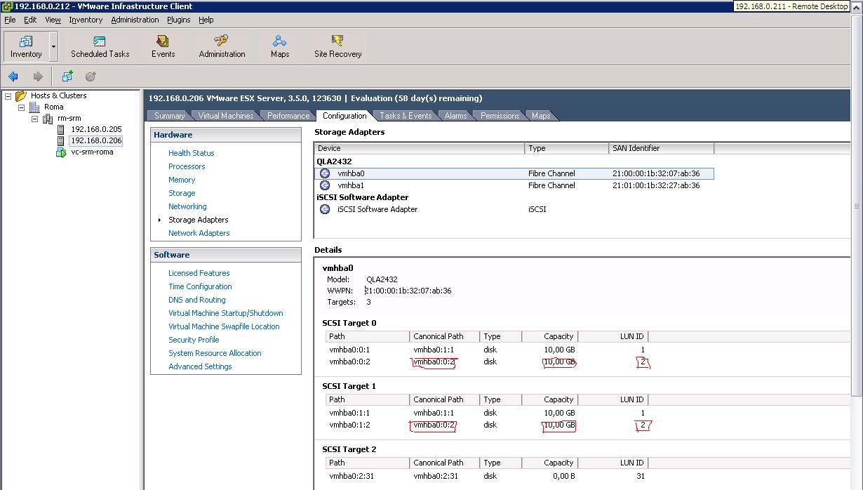
Since we left the parameters above at their defaults (EnableResignature=0, DisallowSnapshotLUN=1), the LUN doesn't show up as a VMware Datastore on any of the hosts in Roma:
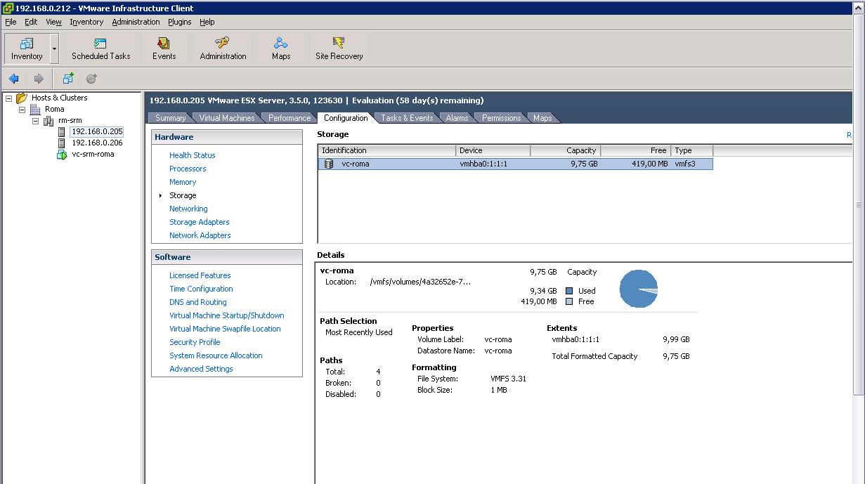
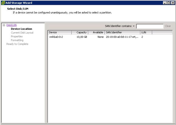
This is the desired behavior since the hosts recognize this is a LUN that is coming from a different storage subsystem (so with a sort of "incompatible" UUID). As a matter of fact, you can manually add a brand new Datastore and the LUN above is showed as available space for a new VMFS file system (which we didn't create as we didn't want to destroy the content):
At this point we changed the DisallowSnapshotLUN parameter to 0 (that setting should read "Allow Snapshot to be imported"):
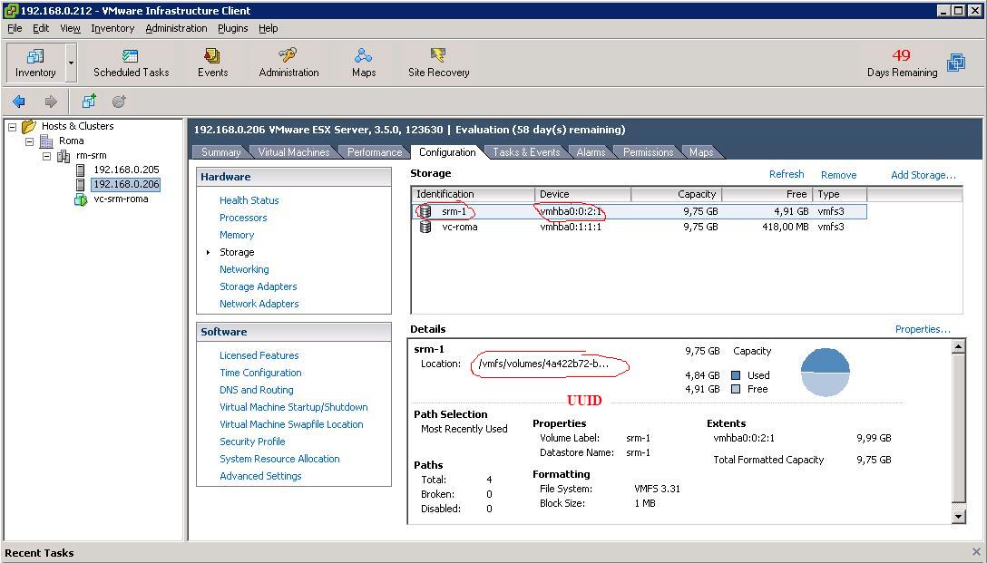
After this change (which doesn't require a reboot of the host), the hypervisor imports the VMware Datastore simply after a rescan of the HBAs:
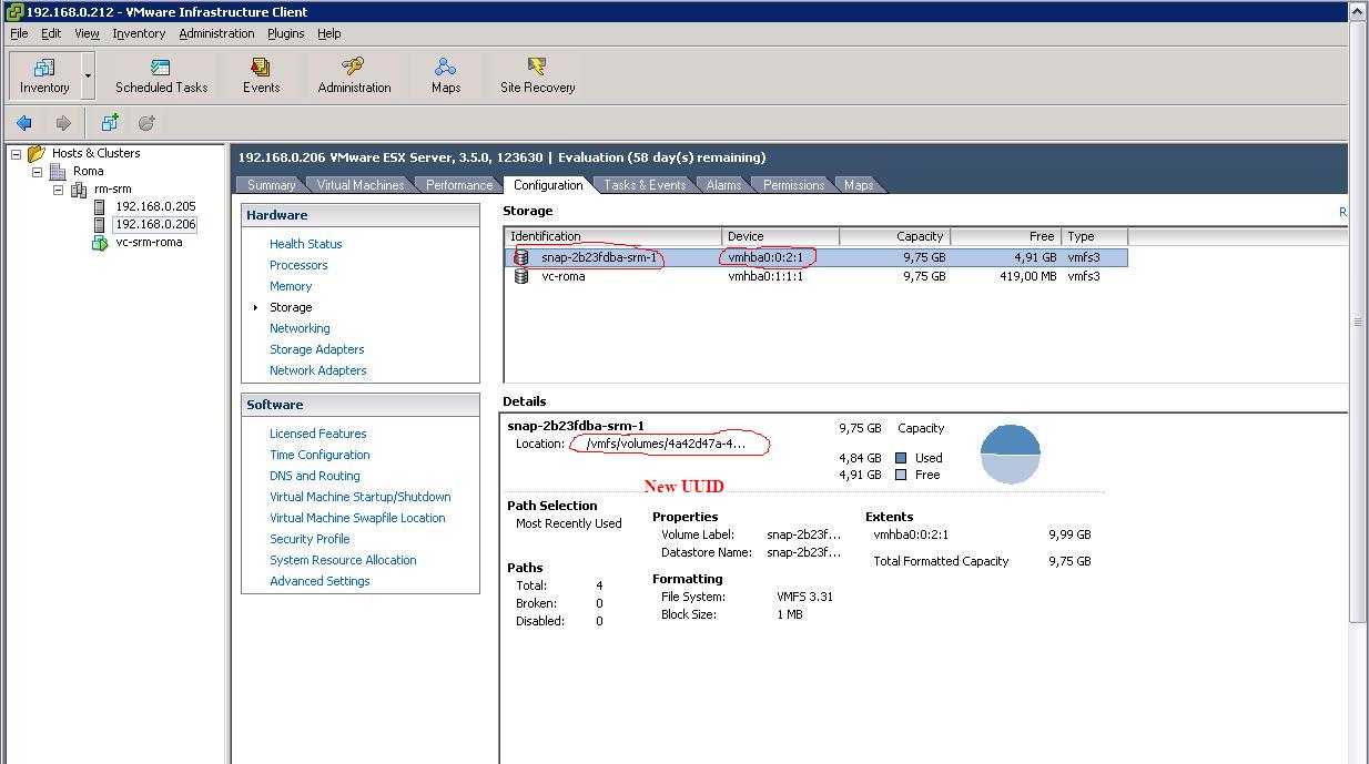
Similarly, by changing the EnableResignature parameter to 1 and rescanning the HBAs, the Datastore gets imported with a new UUID and a new name as you can see from the picture below:
What I have described above (at a very high level) are basically the steps you would need to implement in order to manually deal with a DR procedure. SRM does that under the covers along with a number of other things, such as reconfiguring the VMs on the DR site (alternatively you would have to manually add them to the DR cluster after importing the Datastores). It's a common misconception that VMware SRM is a layer of additional technologies on top of what VI3 already provides (SRM today is not compatible with vSphere, but it should be soon). I think a better way to describe what SRM does is that it's a method to code all the actions you would have to manually implement in order to either test or run a DR Recovery Plan. Many refer to SRM as a "binary coded DR runbook." There is nothing that you can't do if you don't have SRM. But having SRM might save you time... and some risks (manual DR procedures might be error prone).
Site Recovery Manager Setup (Test the Recovery Plan)
In this section, we are going to essentially automate the manual process above by means of a DR orchestrator (in this case, it is called VMware Site Recovery Manager). This article is not intended to be a detailed description of the capabilities of SRM nor a step-by-step guide to its configuration. We will assume from now on the reader has a basic understanding of the product. Before we get into the details it is important to describe the virtual environments (guest OSes) we created in the production site. Notice that there are additional VMs that we have used to host a number of infrastructure services (such as the Virtual Center servers themselves). These VMs generally would be either hosted on external physical hardware or would not be subject to any SRM DR plan anyway. We will focus on what we pretend to be "production VMs" in our lab test. From this perspective we have essentially created three VMs (Web1, Web2, Web3) that we mapped into the 4 LUNs described above. (SRM-1-MILANO, SRM-2-MILANO, SRM-3-MILANO and SRM-4-MILANO) The following picture outlines the mappings.
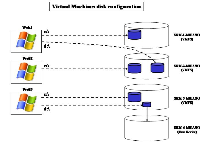
- Web1 has two VMDK files associated to it. One is on the srm-1 VMware Datastore (which in turn is on the SRM-1-MILANO LUN) and another one is on the srm-2.
- Web2 has one single VMDK file associated to it which is on the srm-2 Datastore.
- Web3 is a bit more tricky. It has a VMDK on srm-3 and it also has an RDM (Raw Device Mapping) onto the SRM-4-MILANO LUN. Notice this LUN doesn't have an srm-4 Datastore associated because it's raw. Since the RDM mapping is set to virtual, Web3 has a VMDK pointer (on srm3) to the SRM-4-MILANO raw LUN.
It is of paramount importance to understand how all the VMs interact with the Datastores / LUNs because there might be some consistency dependencies that SRM will have to deal with. In fact, once we have installed SRM as well as the LSI SRA (Storage Replication Adapter), this is what the "Configure Array Managers" window displays:
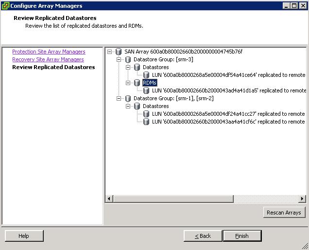
Have you noticed how the various LUNs get grouped together? The first group includes the srm-3 Datastore as well as the SRM-4-MILANO because there is a virtual RDM mapping from a VMDK file on srm-3 onto the fourth LUN. So they are somewhat dependent.
Similarly, there is another group that includes both srm-1 and srm-2. And that's because there are interdependencies as you can depict from the picture with the layout of the VM disk configuration: Web1 is dependent on the first and on the second LUN so they need to be treated as a single Protection Group (you can't split them, as this would split the VM configuration and this wouldn't maintain data consistency!). However, now that you have to treat srm-1 and srm-2 as a single Datastore Group, SRM realizes what the other dependencies are. In fact, Web1 is not the only VM that is hosted (partially) on srm-2: Web2 is hosted on srm-2 and it must be included in the very same Protection Group. This is what you would see from a GUI perspective when selecting this Datastore Group :
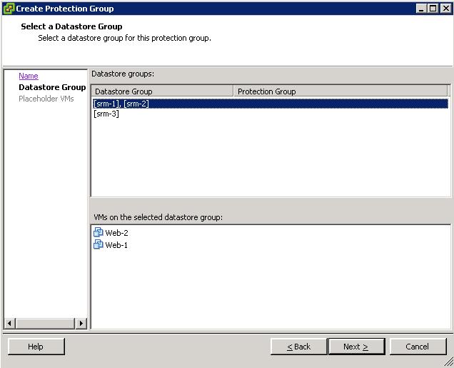
When you select the Datastore or the Datastore Group. SRM automatically displays the VMs that are dependent on that Datastore or those Datastores. That's a read only field. Notice you can't select either srm-1 or srm-2: they are a single entity for SRM.
What we did from here is simple. We created two Protection Groups on the SRM instance hosted on the production site (Milano). These PGs build on top of the srm-1 / srm-2 Datastore Group and the srm-3 Datastore (which includes the RDM on the fourth LUN). Subsequently, we created a Recovery Plan on the DR site (Roma) which contains the failover instructions for these two Protection Groups. That's it.
Our production site is now protected. What we need to do is "Test" our Recovery Plan. One of the advantages of SRM is that it has a built-in intelligence to simulate a DR. Obviously this process is not (and should not be) disruptive: you want to keep the replica of the LUNs in place as well not shutting down the VMs in production to run this test. How do I do so? It's easy. Let's push the Test button on the SRM GUI and go through the plan.
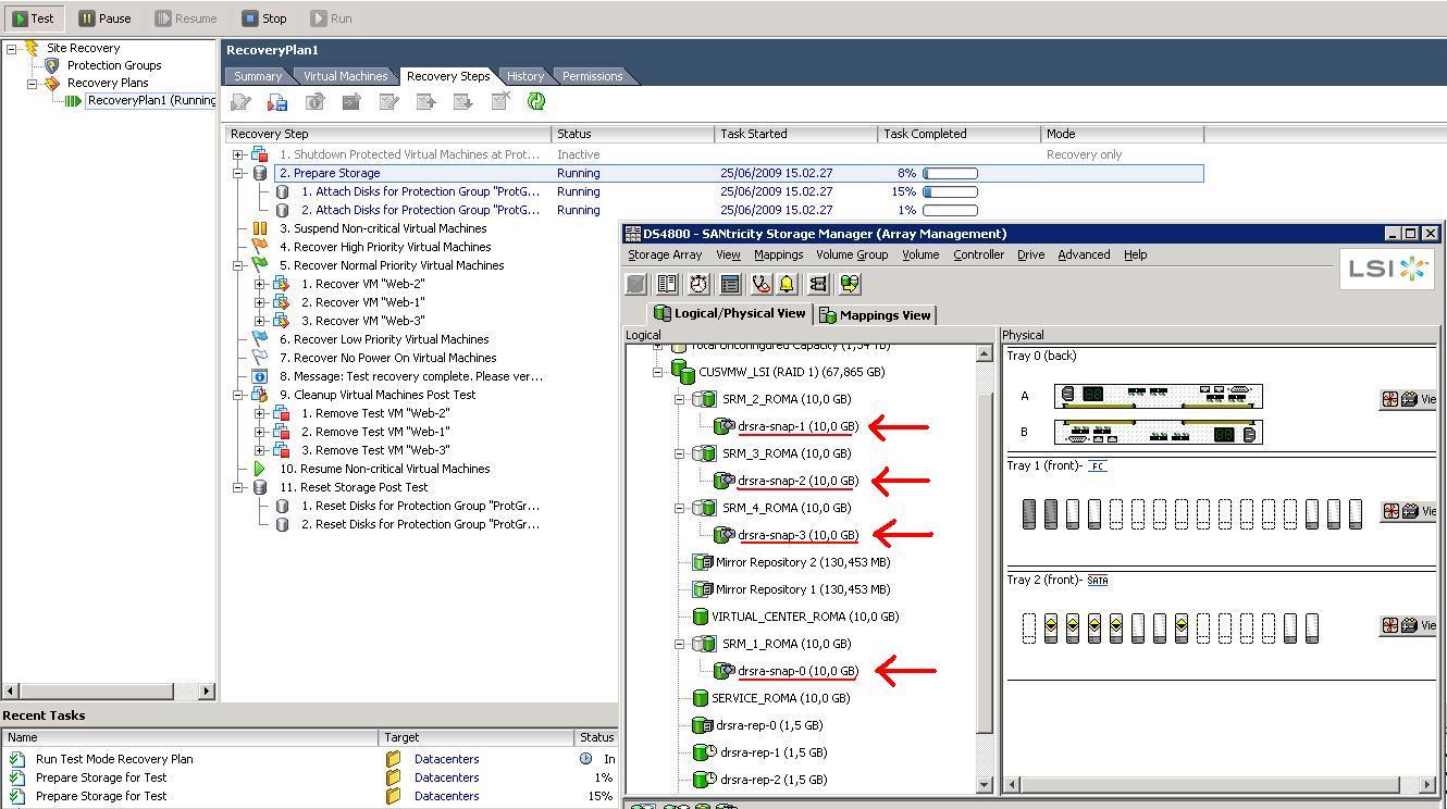
The trick here is that you want to create a dedicated environment (from a storage and network perspective) that doesn't interfere with the production environment. As soon as the test starts, a snapshot of the replicated LUNs is created (at least those that are in the Protection Group associated to the Recovery Plan that is being tested). It's conceptually identical to what we have already done with a manual snapshot (see above), but this time it is SRM that instructs the LSI SRA (Storage Replication Adapter) to create the snapshots and the SRA in turn talks natively to the LSI devices to do so. The SRA is basically the driver that SRM uses to communicate with the actual storage subsystem. You can see the snapshots being created in the next picture:
Background information that you need to understand and be familiar with before you move on...
VMware SRM is configured by default to set the EnableResignature parameter to 1 (that means TRUE) on each of the hosts in the receiving cluster. This means that, independent of the behavior you configured on the hosts, SRM will always resign the LUNs when imported into the remote cluster in the DR site. This will cause the LUNs to be renamed with the (in)famous naming convention snap-xxxx-
If you want to keep things clear and "human readable," you can change the SRM configuration to rename the Datastore to their original names. This is achieved through an SRM configuration file that is vmware-dr.xml and it's located in the C:\Program Files\Site Recovery Manager\Config directory of the SRM server in the DR site. You have to identify the line
and modify it to:
Thanks to Duncan E. and Mike L. for their researches.
It's important to understand that this will not change back the value of the EnableResignature parameter to 0. In fact the LUN will be resigned anyway but SRM will take an extra step to rename the Datastore back to its original name (effectively just deleting the snap-xxxx portion of the new Datastore name).
Not being an expert on this, I can only think that doing so is important when you want to maintain a decent naming convention, especially when you consider that a failback onto the production site would cause SRM to rename the Datastore into something like snap-xxxxx-snap-yyyyyy
Having this said, we have the background to understand the next picture which outlines the storage configuration on the cluster at the DR site in Roma:
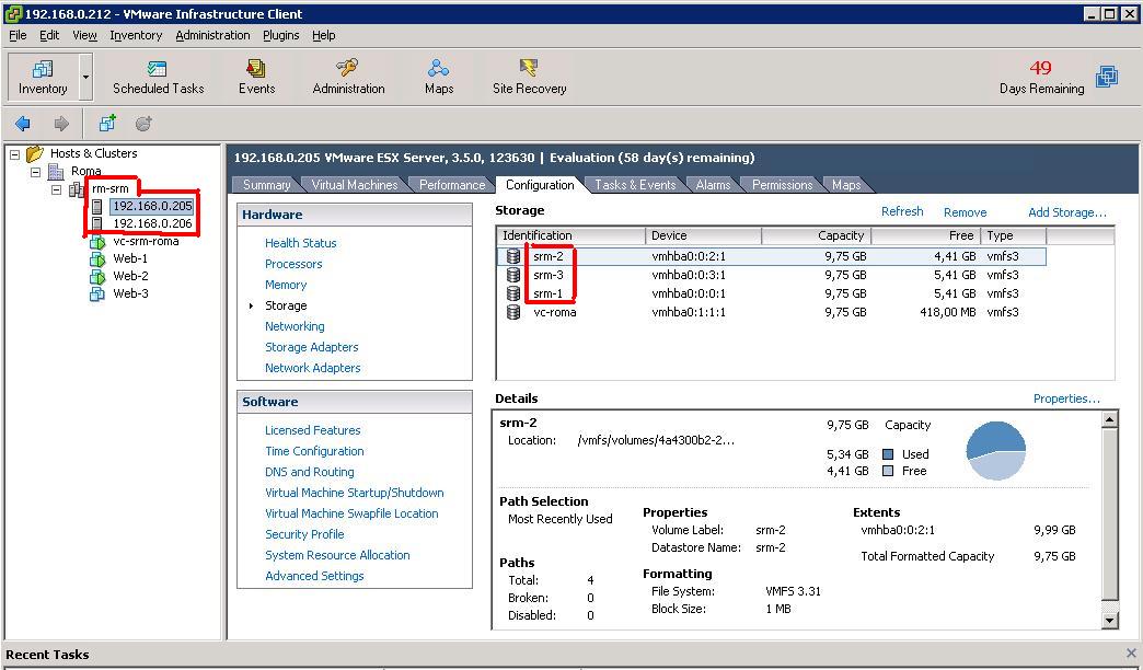
The Datastores have been imported with the original names due to the change in the vmware-dr.xml file. The UUID for the Datastores, however, have been changed since they have been resigned. This is not a problem for SRM because the "place-holder vmx files" that are kept at the DR site do not contain any reference to the disk configuration of the VM. The Datastores are parsed during the execution of the Recovery Plan and the correct disks (with the actual UUIDs) get included in the final vmx prior to the startup of the VM.
Notice that the production VMs are being started off the snapshots that the LSI SRA has created and they are now connected to a so-called "Bubble Network." The Bubble Network is a standard VMware Virtual Switch with no Physical NICs connected to it that gets created for the time of the test. This allows the system administrator to test the restart of a copy of the VMs (currently running in production) without bothering about potential network conflicts. Of course at this time, the replica between the primary and DR sites is still in place and we are still fully protected from a potential disaster.
The test is being executed, and apparently everything has been running smoothly. At this point, SRM pauses for the system administrator to make an evaluation of the test (notice in the SANtricity Storage Manager how the snapshots also have been automatically mapped to the cluster):
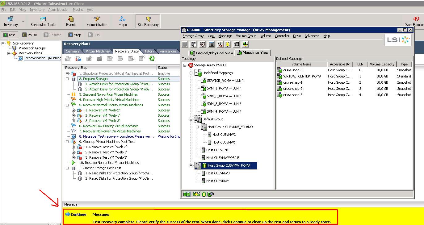
Once the administrator is done with the checks he/she can push the "Continue" button, which essentially rolls back the Test. This, in a nutshell, includes shutting down the VMs in the DR site and deleting the snapshots taken from the replicated LUNs. Everything is now back to normal for the next Test to run (or a disaster to recover from).
Site Recovery Manager Setup (Run the Recovery Plan)
Running the Recovery Plan is different than testing the Recovery Plan. The most important difference is that SRM doesn't create snapshots of the replicated LUNs; rather it uses the replicated LUNs directly. The other difference is that the VMs on the recovery site are connected to the actual physical network and no longer to the "Bubble Network" that is used in the Test. Everything else is pretty similar to what we have seen already.
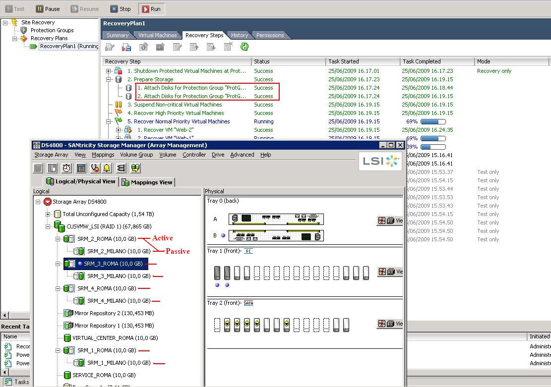
As you can see, SRM instructed the LSI SRA to revert the role of the mirroring: now the LUNs on the DS4800 (the storage server at the DR site in Roma) are "Active" and get replicated onto the "Passive" LUNs on the DS4700 in Milano. Most likely this is not what would happen in a real life disaster. In that case, probably the DS4700 would not be available (due to the disaster) so the SRM would only activate the replicas on the DS4800 in the DR site.
At this point the VMs would be restarted on the cluster in Roma similarly to what happened in the Test scenario (with the exception that they would connect to the actual physical network since they are restarting there to really take over). Remember this is no longer a Test, it's a real Run of a real Recovery Plan. Doing this on a production environment will have devastating results!
At the end of the process, all production VMs (Web1, Web2 and Web3) would be running on the VI3 cluster in Roma which now effectively can be considered the new production site.
Failback
Failback is a nightmare, at least in my opinion. Unfortunately there is not a "Failback Button" on the SRM console. However, you could work on the VMware consoles to create a Recovery Plan that will move all the VMs currently running on the DR site (Roma, for us) onto the original production site (Milano, in our case). Rather than a real failback, I think it's more appropriate to define this as a new failover plan that happens to bring the workloads back to their original positions. VMware has published a useful document that, in chapter 6, describes the steps to failback from an SRM failover. It's a good read. There is only one caveat in that paper that would need further investigation: at some point in the failback process it's suggested to set the DisallowSnapshotLUN parameter on the hosts in the original site to 0 (it would be the hosts in Milano, in our case). This means that when the storage is brought back to the original place, the ESX hosts on the original production site would be able to import the Datastores without resigning them. Since this is done via SRM, it is inconsistent with the behavior we have noticed during the failover. SRM seems to automatically set (on the fly) the EnableResignature to 1 on the hosts where the LUNs are being re-activated, effectively forcing the hosts to re-sign the volumes - and thus making the DisallowSnapshotLUN irrelevant. Further investigation would be required to nail down this inconsistency between the documentation and the behavior we have noticed.
Massimo.
P.S. FOR DUMMIES® is a registered trademark of Wiley Publishing, Inc.