Typical VXLAN Use Case
One of the problems VXLAN is supposed to solve is the possibility to decouple (and abstract) the compute capacity from the underling network configuration. A lot of people whose background is solely in the compute space now know that there is a solution but don’t really get why there is a problem in the first place.
In this post I’ll attempt to describe the problem first and (in brief) the solution later.
Problem statement
The typical example of this scenario is that a VM needs to be deployed in a specific segment of the network. By that I mean a layer 2 broadcast domain. Free compute capacity should ideally drive the placement of this VM. Instead what happens is that what drives the placement is “where that specific network is available” across the number of clusters deployed. In fact, typically, each cluster has its own set of networks available. So if a specific network “is available” in a cluster that is utilized at 80% that’s where you need to deploy your workload, despite there may be another cluster sitting somewhere else doing pretty much nothing.
Why can’t you make that network available to the idle cluster one may argue? That’s the problem I’d like to double click on now.
When people talk about this they tend to mention “the VLAN is not available in that idle cluster”. I believe talking about VLANs confuses the people that don’t have a good networking background (like myself).
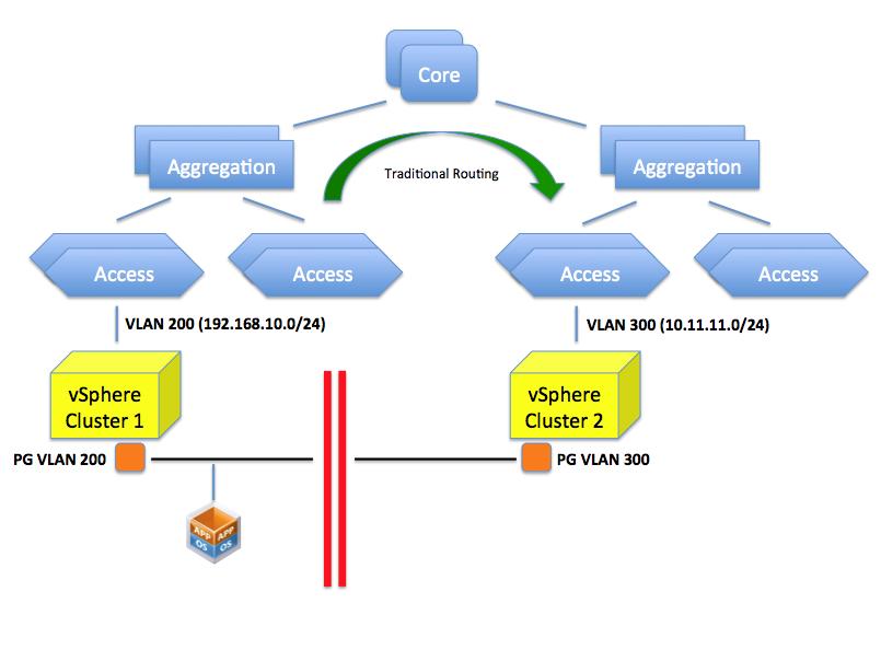
What happens here is that your access layer (TOR switches for example) is configured for one or more VLANs with a specific network. For example VLAN 200 is configured to use a specific network such as 192.168.10.0/24. This VLAN is routed at layer 3 to the other VLANs (or to other networks if you will) available in the infrastructure by means of a router. In a vSphere environment a PortGroup on a vSwitch represents this VLAN and the VLAN 200 (along with potentially others) needs to be made available to a pNIC through a trunk on the Access Layer switch. In a rack far away there may be another TOR switch serving another vSphere cluster. Let’s assume VLAN 300 is available (along others) on this Access Layer switch and, through a trunk on the pNICs, to the cluster. This VLAN is configured with a 10.11.11.0/24 network segment. As you can imagine, placing a VM in either one of the clusters will determine its network personality. In other words it’s not the same thing.
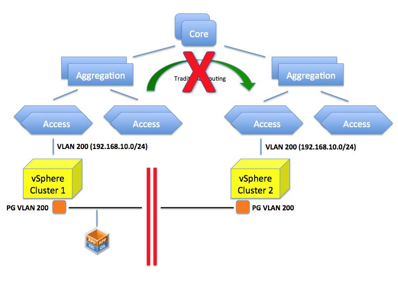
So can’t you just configure VLAN 200 on this TOR? That is the confusing part. This isn’t so much a VLAN problem but rather a routing problem. You could indeed create a VLAN 200 but which IP network are you going to configure it with? If you assign a 192.168.10.0/24 class that doesn’t mean you have created a single layer 2 domain that spans those two VLANs per se (they are considered two distinct separate broadcast domains). You can possibly configure both of them with the very same IP schema but the end result is that:
- VMs in one network won’t broadcast to the VMs in the other network.
- A VM in one network can't reach a VM in the other network (given the address of the other VM is considered a local address so the default gateway won't attempt to route it)
- Every other router/L3 switch will be confused because they won’t know whether to send the packets for 192.168.10.0/24 to the left or right VLAN.
The picture below depicts the limitation mentioned.
If you assign a 10.11.11.0/24 schema to the VLAN 200 in the second cluster you can certainly route between this and the VLAN 200 on the first cluster (whose class is 192.168.10.0/24) but what would the point be if the objective is to create a flat layer 2 across these two switches and ultimately, across these clusters?
So as you can see it’s not so much about “VLANs not being available”. It’s more about routing and segmentations of VLANs based on the configured IP classes the core of the problem.
Can we create a flat layer 2 network across these elements? Yes we can do this by, for example, creating a GRE tunnel (or EtherIP, L2TPv3 or OTV for that matter) that needs to be configured on the ingress and egress aggregation switches. These protocols, in a nutshell, can extend a layer 2 domain across a layer 3 tunnel.
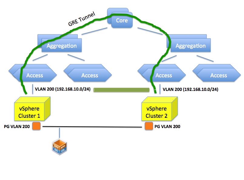
Doing so you are essentially stretching VLAN 200 to the other side of the datacenter. This is different than having two “standalone” VLAN 200’s in different locations of the data center.
This sounds all good but this isn’t usually seen well by network admins because it involves a lot of operational troubles. Consider that in order to create this tunnel all network gears involved in this tunnel (ingress and egress aggregation switches) need to be configured (perhaps manually, perhaps one by one) for this to happen.
The net result is that this doesn’t get done (usually) and the only option is to deploy the VM on the cluster that has visibility of the VLANs that represents the IP network segment the VM needs to end up in.
The Solution
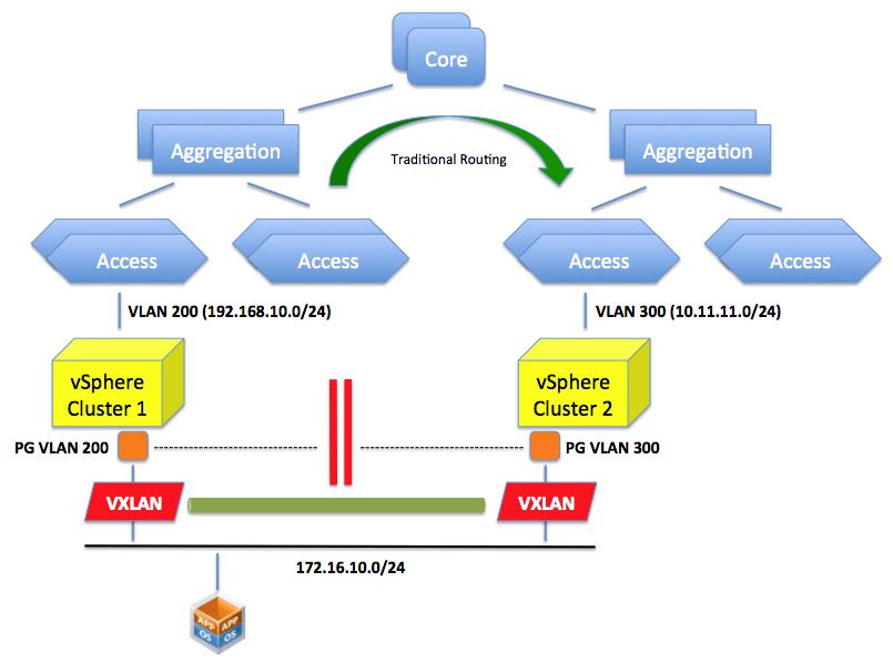
VXLAN provides the solution for the aforementioned problem. By creating an abstraction layer on top of the networking physical infrastructure, the VXLAN technology can bind the two separate layer 2 domains and make them look like one. It essentially presents to the application (or the VM if you will) a contiguous flat layer 2 by connecting (over layer 3) two distinct domains.
This is not different than what the GRE protocol we described above would do. The difference here is that we do this in the software running on the servers leveraging the standard layer 3 routing in the network.
In other words VXLAN encapsulate the layer 2 traffic and send it over traditional layer 3 connectivity. GRE does a similar thing (conceptually at least) but requires the network to be reconfigured to do this encapsulation. VXLAN does this in an abstraction layer running on the server.
A lot has been already said on the technicality VXLAN uses to achieve this (multicasting) and I appreciate there is space for improvements in how it works. This post is not intended to go deep into the solution, as it was more of a double click on the problem and why we need a “solution”.
Please note what we discussed here is one of the two main use cases for VXLAN: creating a flat layer 2 network across a physical layer 3 network.
There is another use case we haven’t mentioned in this brief article: being able to carve out a number of virtual wires from a single VLAN.
Deja Vu
As I was writing this post my mind sort of went back 10 years and I thought this is exactly the same thing VMware did with server virtualization: a static inflexible server infrastructure that couldn’t be adapted easily to run workloads dynamically. The deployment of a new physical server would have taken weeks.
We resorted to a layer of software that could provide the flexibility on top of a static set of resources that was difficult to provision and reconfigure.
The first wave of change came with ESX where you could take an arbitrarily big server and slice it on the fly to create virtual instances out of that static server. In a way this reminds me what VMware did with the Lab Manager logical networks (and now with VXLAN) in the early days where you could take a VLAN a slice it with a right click of the mouse within the context of an application running on the server.
The second wave came with vMotion and DRS where not only you could apply that abstraction at the single server only but we started to tie together loosely coupled physical resources and make them appear as one to the application. In a way this reminds me what we are doing with VXLAN where we take a static routed network backbone and we create these abstracted and flexible virtual wires to make it appear the way we want.
I understand and appreciate this may not be the most efficient way, from a performance perspective, to consume a network. And I hear lots of networking expert saying that. I don’t argue with that. But wasn’t this the same argument for server virtualization in the early days?
Interesting times ahead. Time will tell.
Massimo.